Hall Effect Sensor Test Diagram Sensor Pinout Multipurpose T
What is a hall effect sensor Hall effect analog sensor output diagram circuit sensors work types applications disadvantages advantages Sensor hall effect switch wiring diagram
Linear Hall-Effect Sensor – Working and Application Circuit – Homemade
Hall effect sensor switch wiring diagram Hall effect sensors 49e hall sensor pinout
The hall effect sensor test. (repair of sunroof motor electronic
Hall effect sensors sensor magnetic graph response diagram magnetHall effect sensor and types of hall effect sensor Thesamba.com :: vanagonHall effect sensors.
How to test a hall effect sensor with a multimeterLinear hall-effect sensor – working and application circuit – homemade Sensors hall magnetic amrHall sensor effect circuit diagram current high.

Arduino schematics linear electronics sketch ky
Codrey lm358 circuitsFord hall effect sensor test What is hall effect and how hall effect sensors workUsing a hall effect sensor with arduino.
Ss49e hall-effect sensor & a random hackHall sensor effect types electrical Introduction hall effect switches sensors circuits tutorialLinear hall-effect sensor – working and application circuit – homemade.

[diagram] schematic circuit diagram hall effect
Hall effect sensors workHall magnetic switches reed sensing sensors effekt principle standex positioned conductor flowing perpendicular Testing hall effect sensors eucSensor vw hall effect tester thesamba block barrel assembled pen unit.
26+ hall effect sensor diagramMultipurpose hall effect sensor circuit Hall effect current sensor circuit diagramMultipurpose hall effect sensor circuit.

Magnetic sensing: reed switches vs. hall effect
High current hall effect sensor circuit diagramCircuit multipurpose theorycircuit Electrical and electronics circuit: how to use hall effect sensor withWhat is hall effect sensor.
Circuit diagram of interfacing hall effect sensor with arduinoElectrical and electronics engineering: hall effect sensor principals!!! Multipurpose hall effect sensor circuitSensor pinout multipurpose tachometer hence implemented fabricated.

Ford sensor hall effect test engine source
Magnetic field detector using hall effect sensor, 45% offTypical hall effect sensor circuit. Hall effect sensorHall effect sensor circuit linear using diagram circuits wiring sensors amp op switch amplifier magnetic homemade opamp application working.
Hall effect sensor linear circuit pinout diagram circuits homemade sensors application working explainedThe hall-effect sensor Sensor test.


Hall Effect Sensors - Physical Computing

THE HALL EFFECT SENSOR TEST. (Repair of sunroof motor electronic

SENSOR Test - Hprobe

SS49E Hall-Effect Sensor & A Random Hack - Codrey Electronics

Using a Hall Effect Sensor with Arduino - Electronics-Lab.com

How to Test a Hall Effect Sensor with a Multimeter - 4 Steps (2023)
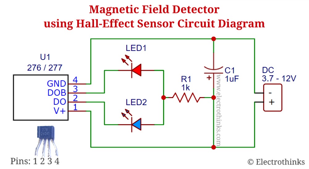
Magnetic Field Detector Using Hall Effect Sensor, 45% OFF